Fast convergence - MPLS
Introduction
What do we mean by network convergence?
Convergence
Routing convergence is the transition from a routing AND forwarding state to another state.
Convergence is typically triggered by a change in the topology, which can be either sudden, in the case of a failure, or planned, in the case of maintenance (hardware upgrades, firmware updates, config. changes).
Convergence is a distributed process, during which routers might have an inconsistent view of the network.
Why should we care?
Problem: inconsistency
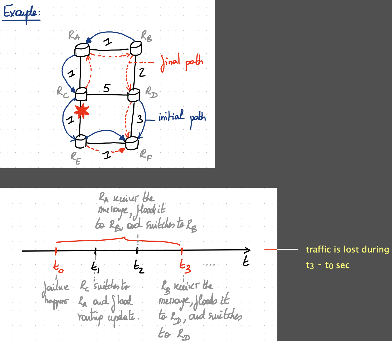
Transiently inconsistent routing and forwarding state can lead to traffic loss.
These losses happen because:
- routers do not detect changes immediately and therefore forward traffic in a “blackhole”
- annoying
- the forwarding paths contain forwarding loops.
- VERY annoying
Not all transient states lead to traffic losses. In practice, operators are mainly concerned about retrieving connectivity, not avoiding transient states.
What composes the convergence time?
There are 4 main sources of convergence delay:
| Scope | Order | Description | Time taken |
|---|---|---|---|
| local | 1 | detecting the failure | takes $O$(milliseconds) |
| global | 2 | communicating the failure | takes $O$(milliseconds) |
| global | 3 | recomputing forwarding state | takes $O$(milliseconds) |
| global | 4 | updating forwarding state | takes $O$(# prefixes), can be very slow |
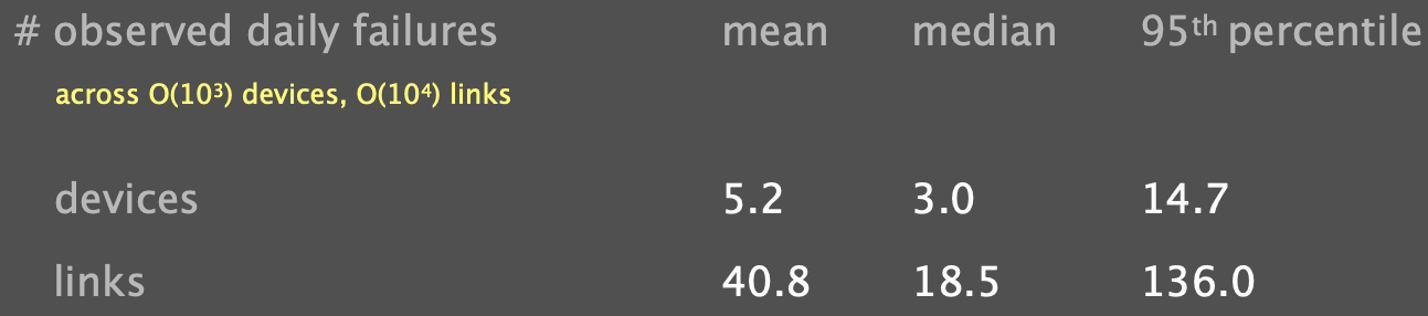
Do failures happen that frequently?
Yep… especially in large networks
Fast convergence in IP networks
Fast detection
Goals:
- Fast detection
- High accuracy
- Low overhead
Possible mechanisms:
- Rely on physical/link layer support
- Rely on “hello”/beacons
Rely on physical/link layer support
Some physical/link layers, such as optical layers, can detect failures through the loss of light, a carrier signal.
Example:
- Synchronous Optical Networking
- Synchronous Digital Hierarchy
- Dense Wavelength Division Multiplexing
Pros:
- As fast as you can get
- few milliseconds
- (Virtually) no overhead
Cons:
- Only works for some physical/link layers
- e.g., not in Ethernet
- Does not detect certain kinds of failures.
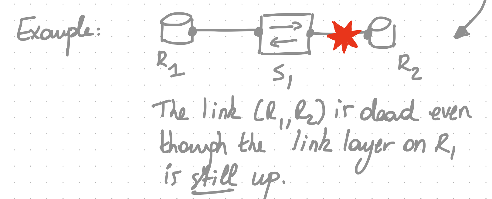
Rely on “hello”/beacons
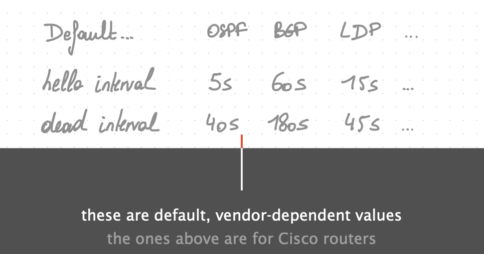
The idea here is to have adjacent routers regularly exchange “hellos” and signal a failure whenever $k$ of them are missed in a row. By default, each routing protocol comes with its own hello-based protocol. Each one allows the operator to configure:
- the frequency at which hellos are generated
hello interval
- the interval after which, not receiving a single hello, the protocol declares the peer dead
dead interval
Pros:
- Works on any router platform
- Detects a wider range of failures because it actually tests the forwarding path.
Cons:
- SLOW
- HUGE overhead
- To decrease the detection time, one has to stress the control plane a lot.
- This is incredibly wasteful as each protocol is basically doing the same thing without exchanging any info.
Bidirectional Forwarding Detection (BFD)
The modern way to solve these two problems is to rely on ONE protocol-agnostic hello-based service that can directly run on hardware. This service is known as Bidirectional Forwarding Detection. 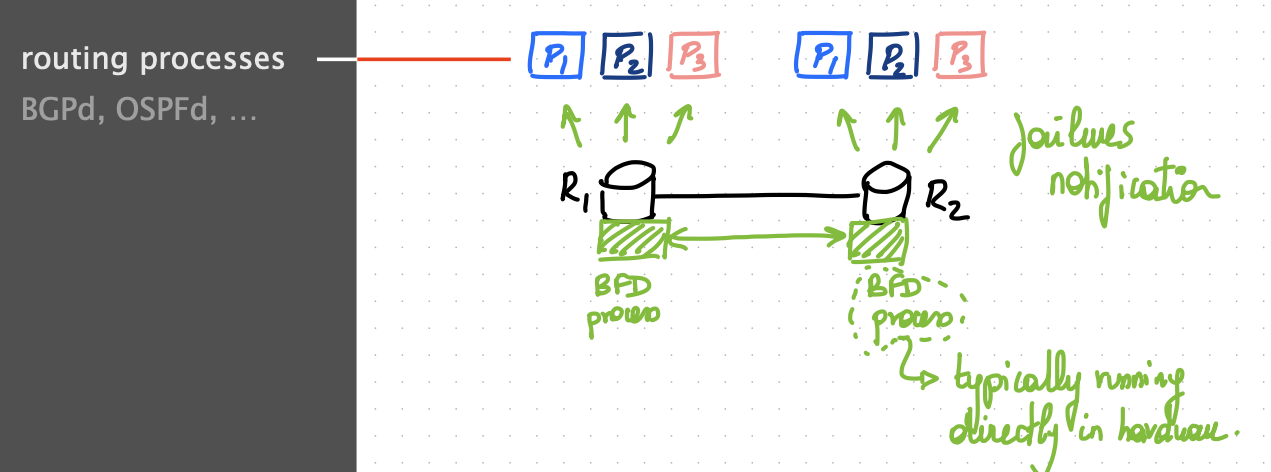
The hello interval can be as low as $50$ ms, with dead interval around $150$ ms
- much faster than protocol-based detection.
Pros:
- Fast detection
- Low overhead
- High coverage
- Because BFD tests the actual forwarding path, not just the interface liveness
Cons:
- Not all routers can run BFD on hardware
Conclusion
- Use link-layer mechanisms whenever available
- Complement these mechanisms with a hardware-based BFD service, if available
- Fallback on protocol-based detection as a last resort.
Fast propagation
This is pretty easy to solve. Essentially, we want two ensure $2$ things:
- The flooding of the failure notification happens immediately after the detection.
- The flooded packets are sent with absolute priority over the rest of the traffic.
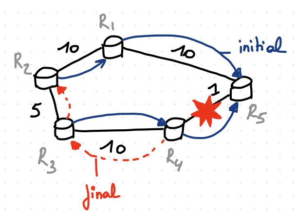
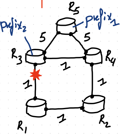
Note that for convergence to happen, not necessarily all routers need to hear about the failure.
In the example above, “only” R3 and R4 need to be notified about the failure to retrieve connectivity towards R5. At the same time, “only” R1 and R5 need to be notified about the failure to retrieve connectivity towards R4.
Fast computation
For shortest-path-based protocols such as OSPF and ISIS, this is not a problem anymore:
- Dijkstra’s algorithm time complexity $O(E\log V)$
- Computing an entire shortest-path tree in a HUGE network only takes a few milliseconds nowadays.
- In addition, incremental shortest-path computation can help scaling this even further.
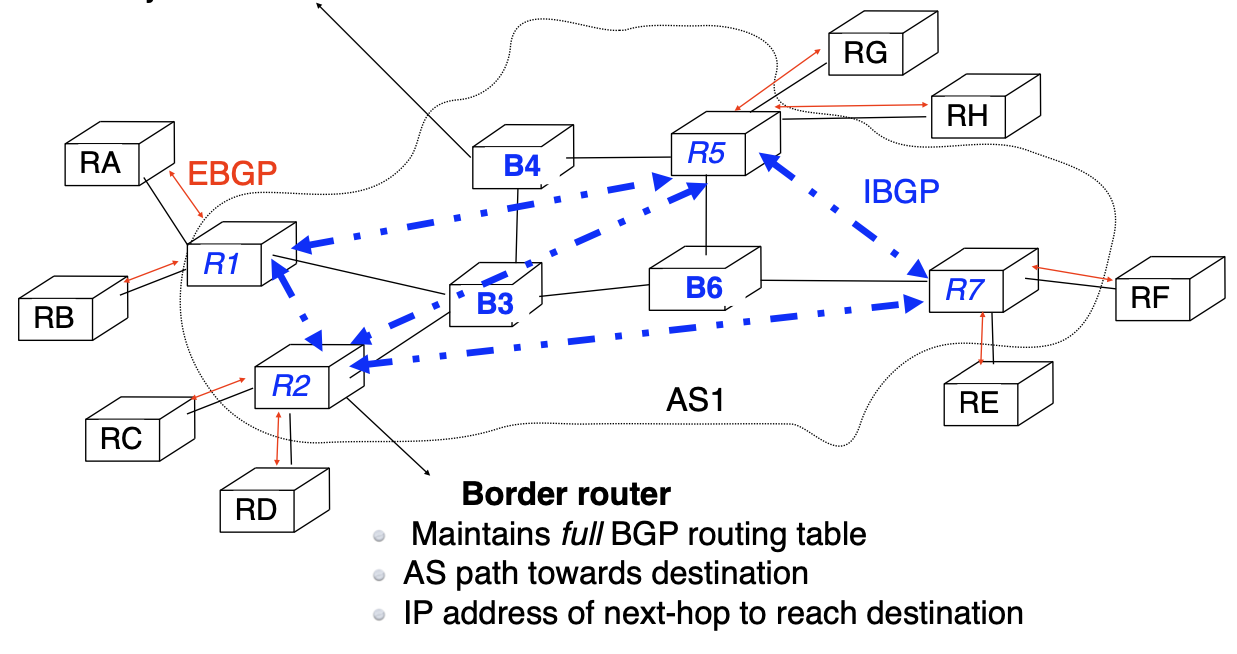
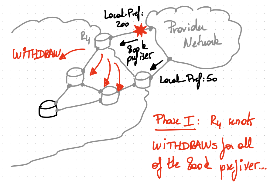
For BGP, this still remains a problem:
- the computation is done per-prefix
- oftentimes, BGP routers do not even know an alternate path and literally need to “hunt” for it.
Example
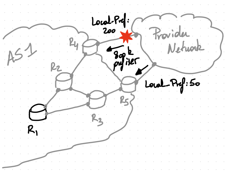
Prior to the failure, all of the internal routers in AS1 only know one route to reach each of the 800k prefixes: via R4. This is because R5 does not advertise its eBGP routes as they have a smaller local-preference.
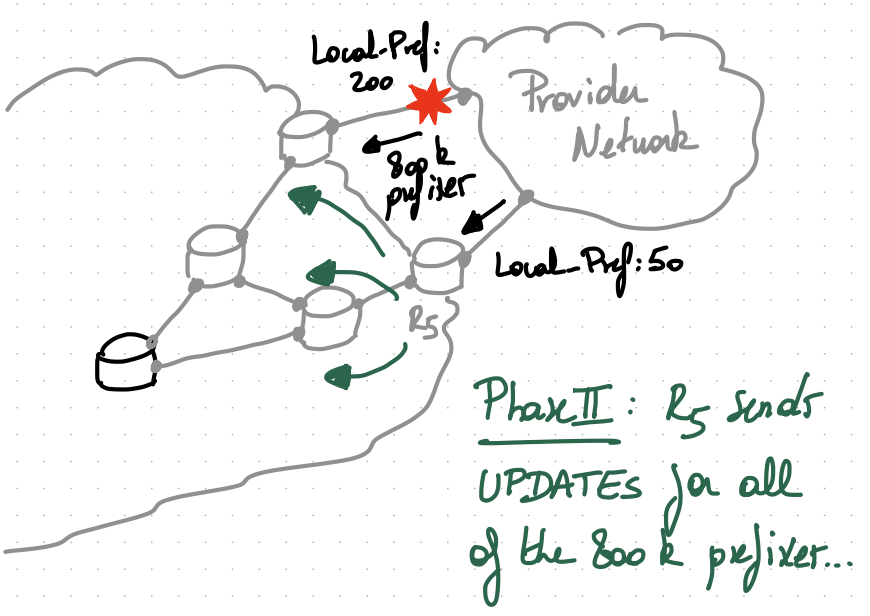
One way to avoid this problem is to force R5 to advertise its external routes, even if it does not choose them as best.
Multiple BGP extensions allow that. Of course, it comes at the cost of having internal routers carrying possibly WAY more routes in their routing table.
The tradeoff between scalability and speed is rather typical in networking.
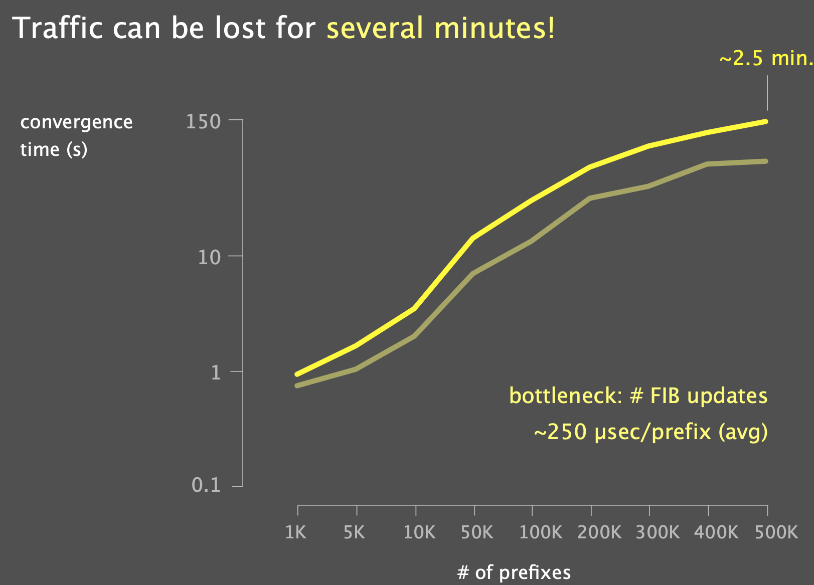
Fast updates
Updating the Forwarding Information Base (FIB) is typically the key bottleneck to overcome in the convergence problem: \(\text{Total Update Time} = \text{num prefixes } \cdot \text{average update time per prefix}\)
On average, it sits in the order of $100$s of $\mu s$:
- for a full BGP table of around 800k prefixes: \(800.000\cdot 250\mu s=200s\)
“Cheap trick”: prioritize FIB Updates according to how much traffic each prefix sees.
- Pre-compute the backup state
- Pre-load it in the reorganized FIB
- Activate the pre-loaded backup state upon detecting a failure IGP $\rightarrow$ Loop-Free Alternates (LFA) BGP $\rightarrow$ Prefix-Independent Convergence (PIC)
Loop-free Alternates
Intuition
A LFA is a neighbor for which you know that you can deviate the traffic impacted by a given failure and that traffic will not come back to you.
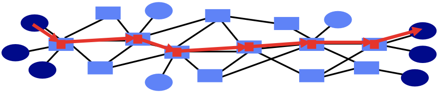
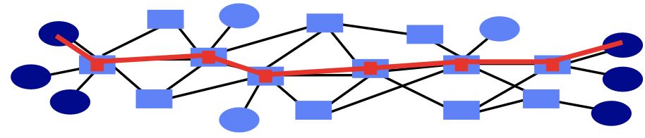
LFA Example
 {width=”50%”}
R3 is a LFA of R1 for the failure of $R1\rightarrow R2$ since R3 does not use R1 to reach R2.
Definition
A neighbor N can provide a loop-free alternate to S for a destination/prefix $d$ if and only if \(MinDistance(N,d) < MinDistance(N,S) + MinDistance(S,d)\)
How to compute link-protecting LFA on a router X
link-protecting LFA: direct neighbors which provide LFAs for all destinations whose next-hop goes over a given link
1
2
3
4
5
6
7
8
9
For all links (X,R):
  For all direct neighbors N != R:
    candidate_N = True
    For all destinations d whose next-hop is R:
      if SPT(N,d) includes (X,R):
        candidate_N = False
        break
      if candidate_N:
        add (X,N) as candidate link-protecting LFA for (X,R)
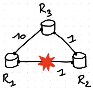
One can easily extend this algorithm to compute per-prefix LFA. Take a look at this topology:
- R2 is not a per-link LFA for R1 as R2 uses R1 to reach prefix 2.
- But, R1 is a per-prefix LFA for R1 for prefix 1.
- because $dist(R2,prefix_1)<dist(R2,R1)+dist(R1, prefix_1)$
Depending on the network topology, a subnet of the links and/or prefixes will be protectable using LFA/per-prefix LFA.
- Some design patterns, such as triangles, lead to high coverage.
- Also, $coverage(perlinkLFA)\leq coverage(perprefixLFA)$
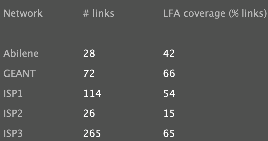
In practice, LFA coverage is highly topology-dependent
Increasing LFA’s coverage with Remote LFAs
Let’s look at another example, a ring-based network:
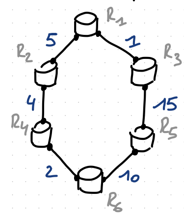
In this topology, R1 does not have a per-link nor a per-prefix LFA to R6, because R3 uses R1 to reach R6 in the pre-convergence state.
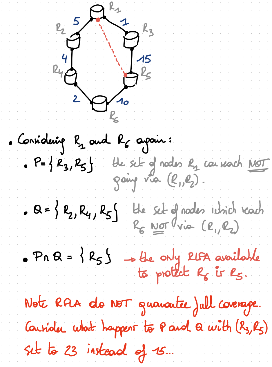
Remote LFAs enable to increase the LFA coverage by allowing a router to use remote, non neighboring routers as repair nodes by tunnelling to them (using IP-based tunnels or MPLS).
While R3 uses R1 to reach R6, it does not use R1 to reach R5.
R5 reaches R6 directly.
By encapsulating its R6-directed traffic to R5 and sending that encapsulated traffic to R3, R1 can retrieve connectivity.
How do we compute remote LFAs?
Given $D_{opt}(a,b)$, a function that returns the shortest-path distance between $a$ and $b$,
- On route
x, - For every destination
x;- Let
nhbe the pre-converge next-hop used byxto reachy - Let
Pbe the set of nodes thatxcan reach without traversing $(x,nh)$ - Let
Qbe the set of nodes that can reachywithout traversing $(x,nh)$ - Let
candidates_RLFA=P && Q - Return
candidates_RLFA
- Let
(R)LFA gives us a simple condition a route can check locally to know to which neighbor it can safely redirect traffic to. The next question now becomes:
- How do we organize the FIB to allow for a fast archiviation of the backup state?
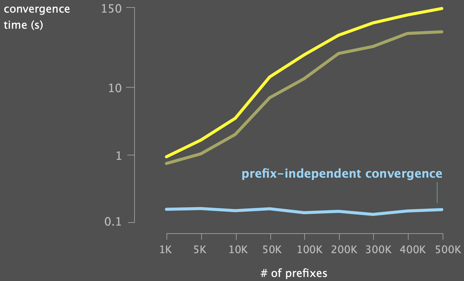
Prefix-independent Convergence
Goal: enable routers to quickly switch over to pre-installed alternate paths upon failures that affect BGP routes
Make BGP as fast to converge as IGP
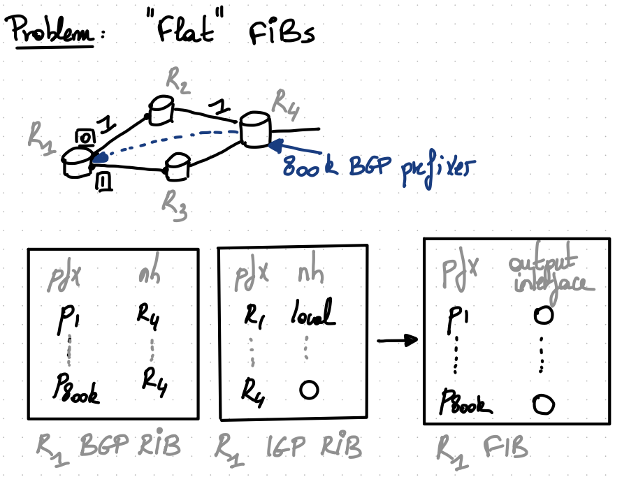
Upon the failure of $(R1,R2)$ link, R1 has to perform $800$k updates to its FIB…
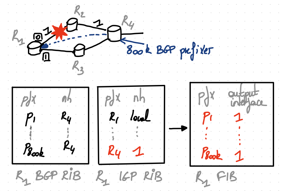
The fundamental problem is that the dependency between BGP next hop and the IGP one is NOT maintained in the FIB. It is flattened.
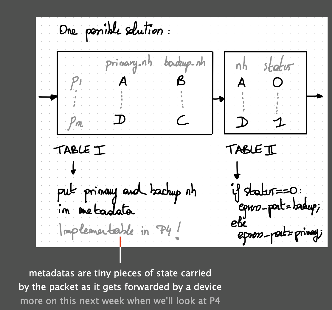
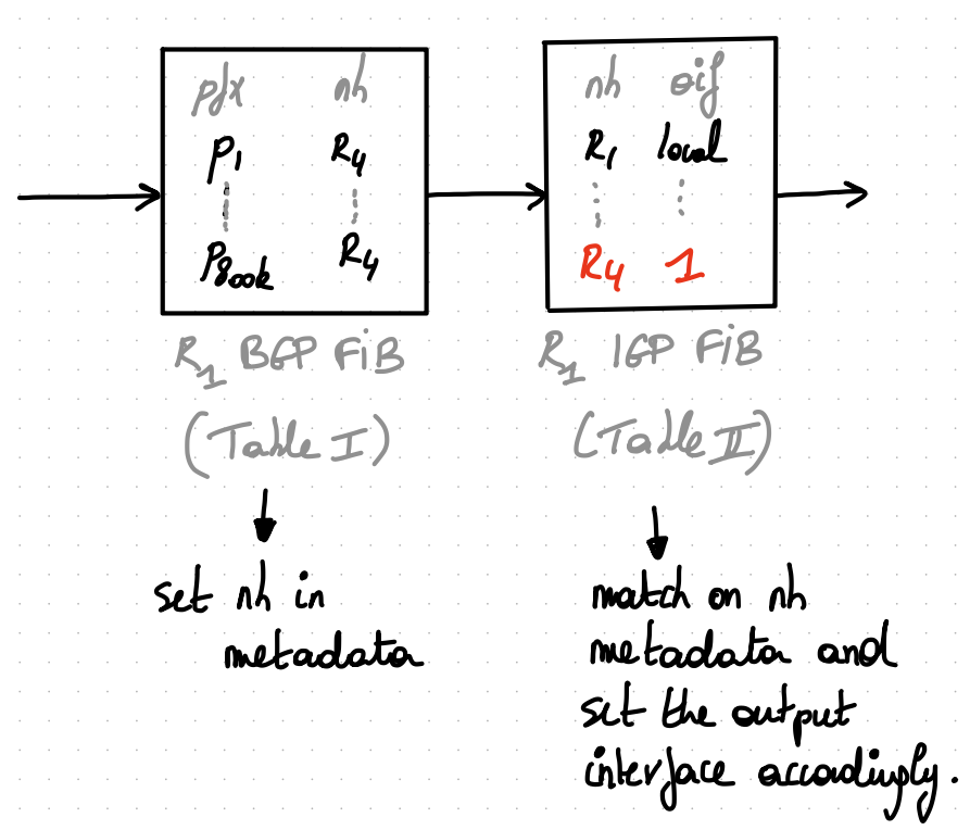
Solution
Maintain the hierarchy between BGP next-hops and IGP next-hops in the FIB as well. (easy to implement in P4)
Intro to MPLS
Packet Switching
Source sends information as self-contained packets that have an address.
- Source may have to break up single message in multiple
- Each packet travels independently to the destination host.
- Routers and switches use the address in the packet to determine how to forward the packets
- Destination recreates the message.
Analogy: a letter in surface mail.
Circuit Switching
- Source first establishes a connection (circuit) to the destination.
- Each router or switch along the way may reserve some bandwidth for the data flow
- Source sends the data over the circuit.
- No need to include the destination address with the data since the routers know the path
- The connection is torn down.
Example: telephone network.
Traditional circuits: on each hop, the circuit has a dedicated wire or slice of bandwidth.
- Physical connection - clearly no need to include addresses with the data
Advantages, relative to packet switching:
- Implies guaranteed bandwidth, predictable performance
- Simple switch design: only remembers connection information, no longest-prefix destination address look up
Disadvantages:
- Inefficient for bursty traffic (wastes bandwidth)
- Delay associated with establishing a circuit
Can we get the advantages without (all) the disadvantages?
Virtual Circuits
Each wire carries many “virtual” circuits.
- Forwarding based on virtual circuit (VC) identifier
- IP header: src, dst, etc.
- Virtual circuit header: just “VC”
- A path through the network is determined for each VC when the VC is established
- Use statistical multiplexing for efficiency
It can support wide range of quality of service.
- No guarantees: best effort service
- Weak guarantees: delay < 300 msec, …
- Strong guarantees: e.g. equivalent of physical circuit
IP meets virtual circuits - MPLS
Core idea: forward according to labels, in-between L2 and L3
- MPLS is often referred to as a layer 2.5 protocol
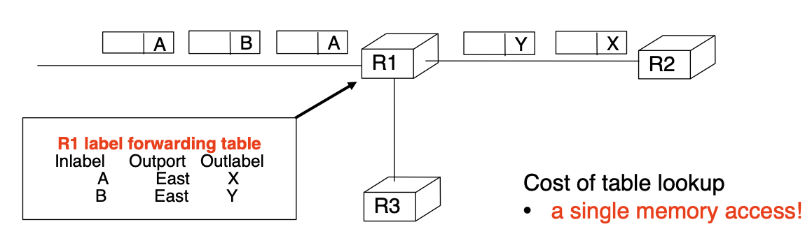
Label swapping in a nutshell
On packet arrival, the router analyses the input packet label. Using its label forwarding table, the router then decides:
- Output packet label
- Output interface
Integrating label swapping and IP
We need to solve $3$ problems
- What do we use as packet label?
- Insert special 32 bits headers in front of the IP header
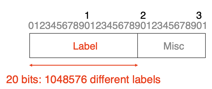
- Insert special 32 bits headers in front of the IP header
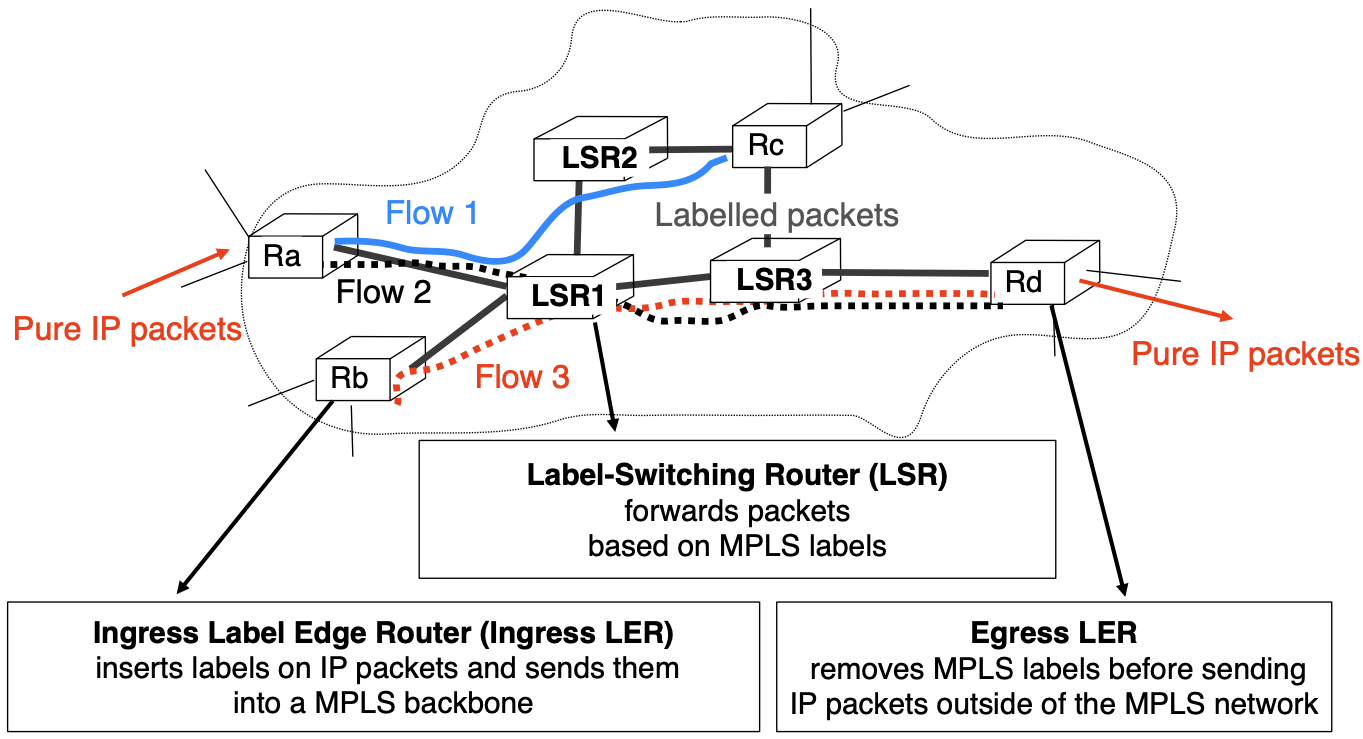
- What is the behavior of a LSR?
- What is the behavior of an ingress LER?
Label Switch Router (LSR)
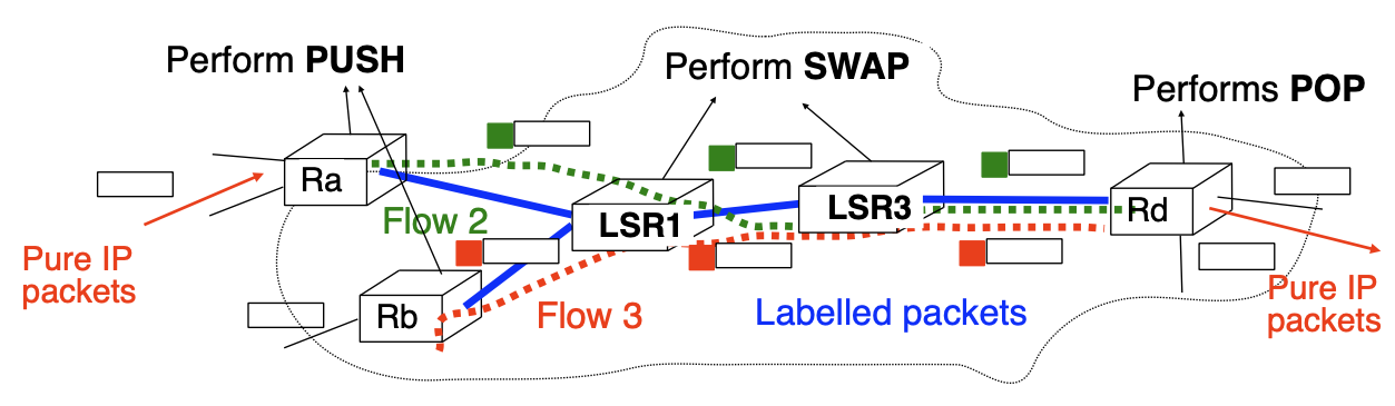
MPLS data plane allows for $3$ operations on a labelled packet:
PUSH- insert a label in front of a received packet
SWAP- change the value of the label of a received labelled packet
POP- remove the label in front of a received labelled packet
LSRs forward traffic according to their label forwarding tables: 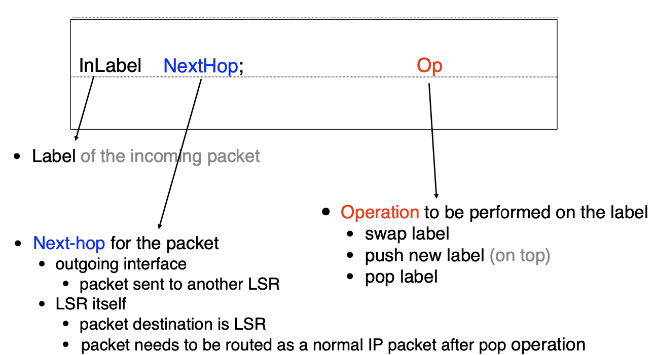
Label forwarding table: examples entries 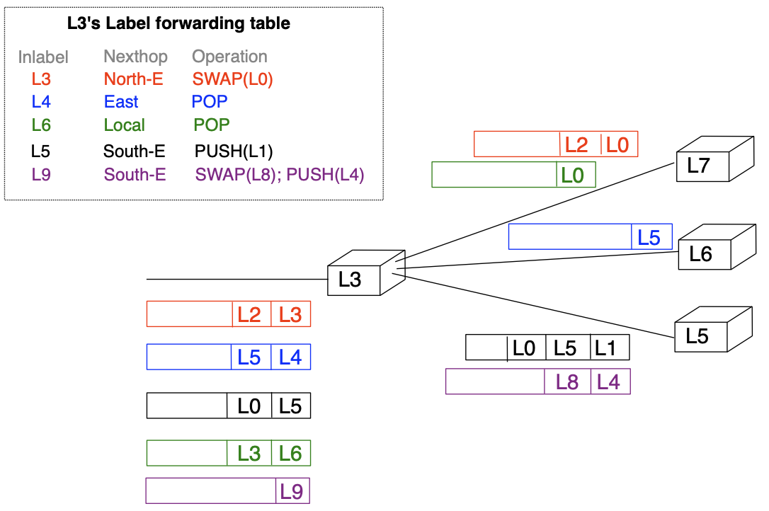
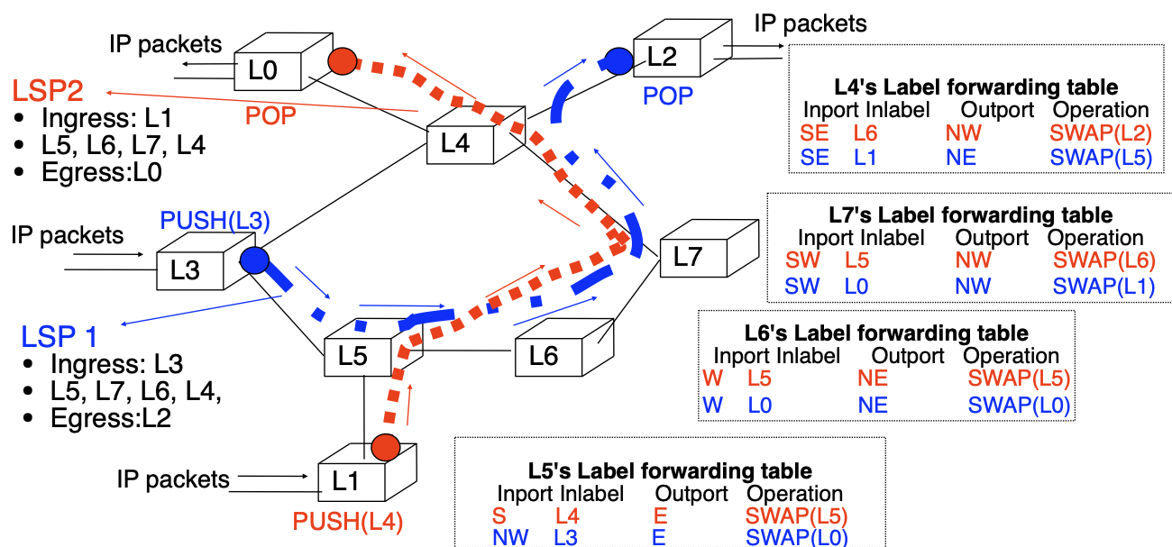
A Label Switched Path (LSP) is a unidirectional tunnel between a pair of routers.
LSP:
- a path followed by a labelled packet over several hops starting at an ingress LER and ending at an egress LER
- an LSP is required for any MPLS forwarding to occur
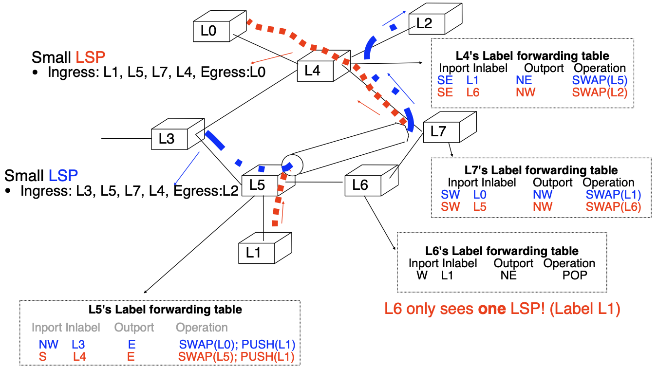
Label stacking helps to scale by introducing a LSP hierarchy
How to support hierarchy of LSPs?
- it should be possible to place small LSPs inside large LSPs
- ideally, there should be no predefined limit on the number of levels supported
Solution adopted by MPLS:
- each labelled packet can carry a stack of labels
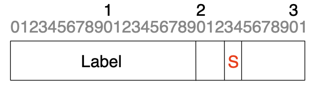
- label at the top of the stack appears first in packet
S=1if the label is at the bottom of the stackS=0if the label is not at the bottom of the stack
MPLS and label stacks
How does ingress Label Edge Router (LER) determine the label to push on an IP packet?
Principle:
- Divide the set of all possible packets into several Forwarding Equivalence Classes (FEC)
- A FEC is a group of IP packets that are forwarded in the same manner (e.g. over the same path, with the same forwarding treatment)
- Examples:
- All packets sent to the same destination prefix
- All packets sent to the same BGP next hop
- Examples:
- A FEC is a group of IP packets that are forwarded in the same manner (e.g. over the same path, with the same forwarding treatment)
- Associate the same label to all the packets that belong to the same FEC
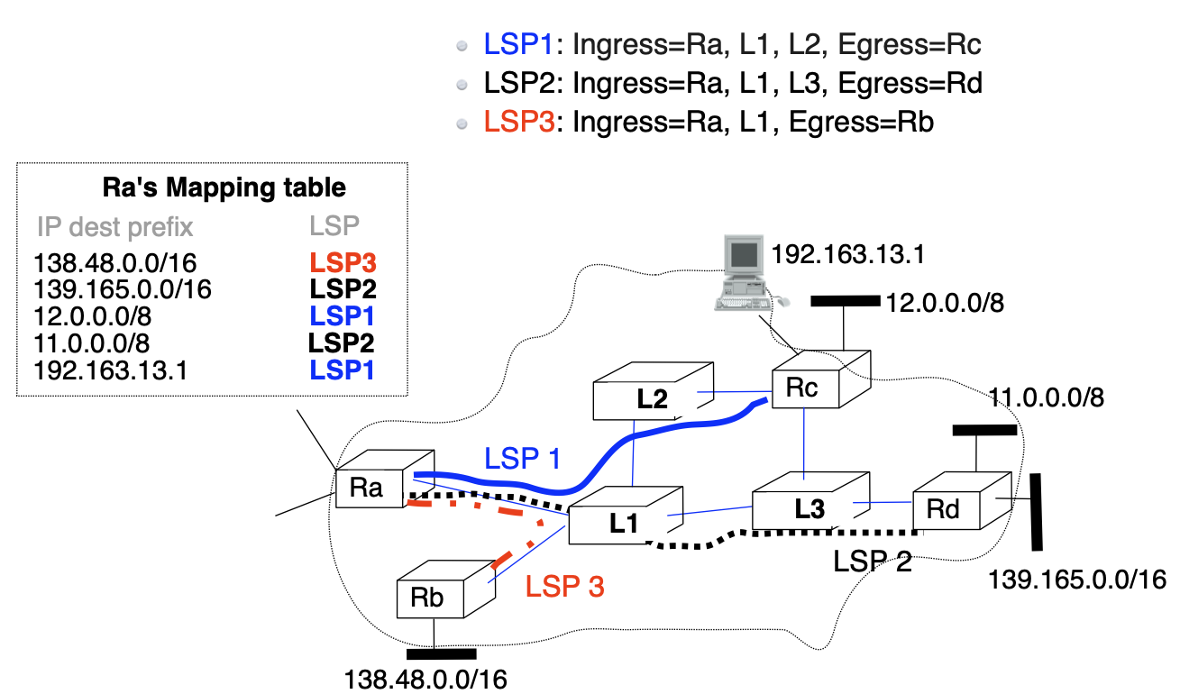
Destination-based packet forwarding
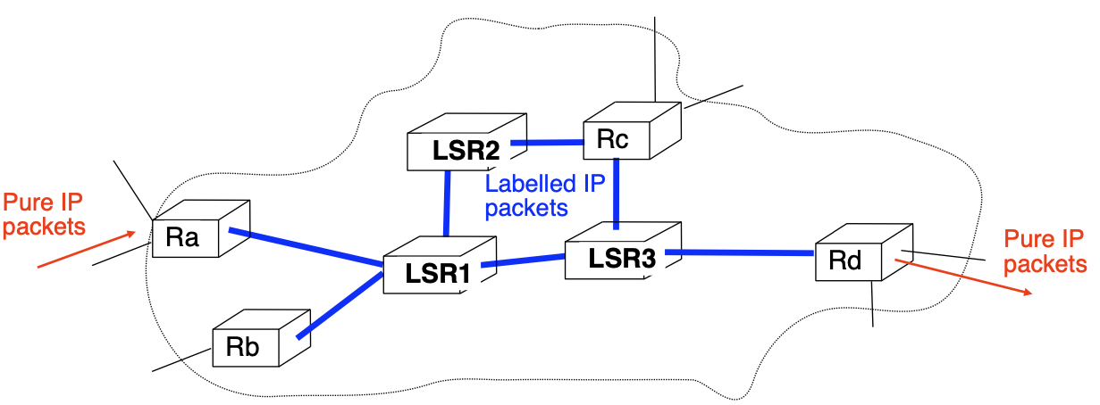
How to provide transit service when:
- Edge LERs are able to attach and remove labels
- Edge LERs and Core LSRs run IP routing protocols and maintain IP routing tables
- Core LSRs can only forward labelled packets
Manual solution
Create full mesh of LSPs between all edge LSRs
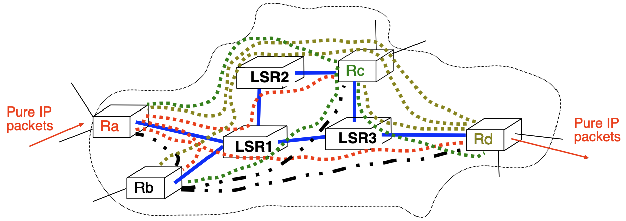
Problems to be solved:
- $N$ edge LSRs $\rightarrow N(N-1)$ unidirectional LSPs
- How to automate LSP establishment?
- How to reduce the number of required LSPs?
How to automate LSP establishment?
How to fill the label forwarding tables of all LSRs in a given network?
- Use a dedicated protocol to distribute FEC-label mappings
- LDP: Label Distribution Protocol
- RSVP-TE: Resource Reservation Protocol—Traffic Engineering
- Piggyback FEC-label mappings inside messages sent by existing routing protocols
- possible if routing protocol is extensible
- BGP can be easily modified to associate label with route
- possible if routing protocol is extensible
MPLS in large, IP-based ISP networks
- eBGP on border routers
- current full BGP Internet routing table
- ~1M active routes
- current full BGP Internet routing table
- iBGP full-mesh
- 4 border, 3 core routers
- 24 iBGP sessions
- 4 border, 3 core routers
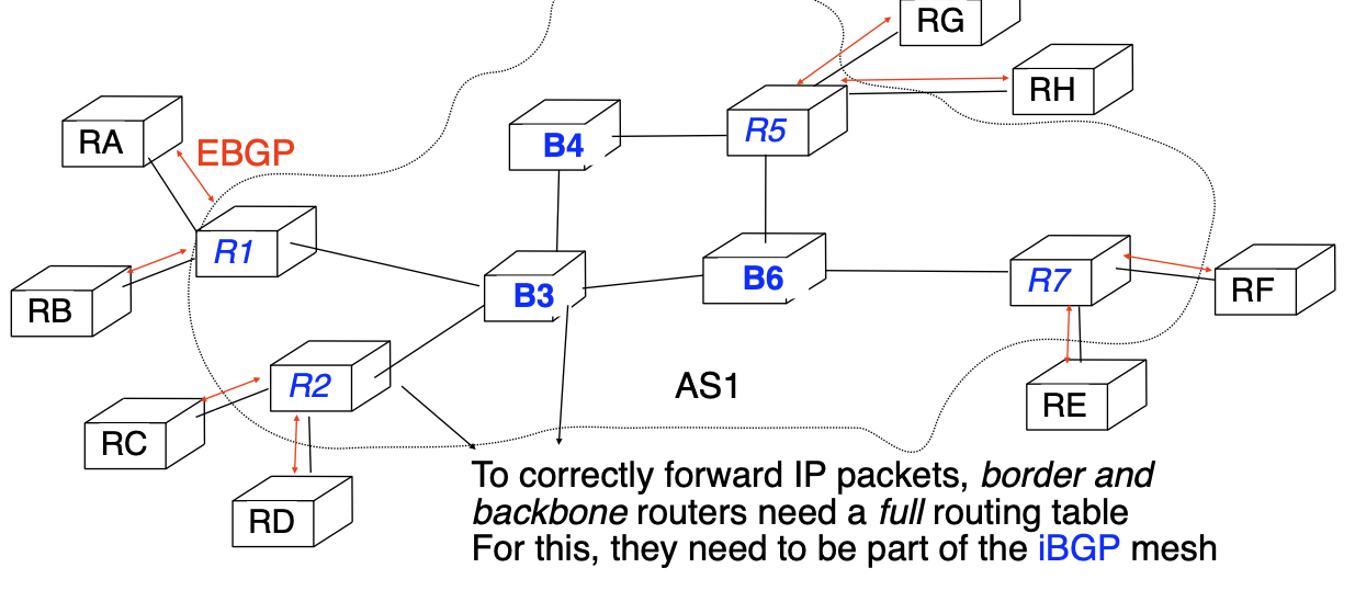
MPLS enables to build BGP-free backbones
Backbone router
- Maintains internal routing tables + label forwarding table
- only knows how to reach routers inside ISP